Following up on our previous exploration into restoring the tweeters of the classic Pioneer CS-88a speakers, we now turn our attention to another crucial aspect of audio rejuvenation: recapping the crossover network. While perhaps less intricate than tweeter repair, refreshing the crossover is a straightforward process that can significantly enhance the performance of your vintage speakers. If you haven’t already, ensure all drivers are safely removed from your CS-88a cabinets. Remember to label all wire connections for easy reassembly. This provides ample space to access and remove the crossover unit, which is typically screwed into the cabinet. Once accessible, carefully unscrew the crossover assembly from the cabinet, being mindful not to damage the screw heads if they are tightly secured.
The Pioneer CS-88a crossover, while not visually complex, is a critical component in directing audio frequencies to the appropriate drivers. It consists of capacitors, resistors, and inductors, along with adjustable knobs that subtly alter the speaker’s sound profile. The resistors in these vintage crossovers are generally robust wire-wound types that rarely require replacement unless physically damaged. Similarly, the inductors are typically reliable and don’t usually degrade over time.
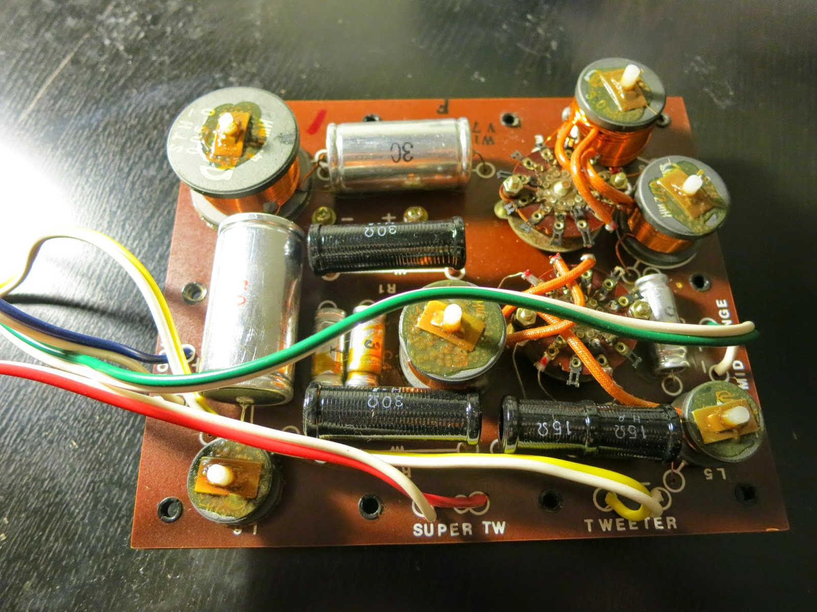 Pioneer CS-88a crossover unit removed from the speaker cabinet for capacitor replacement
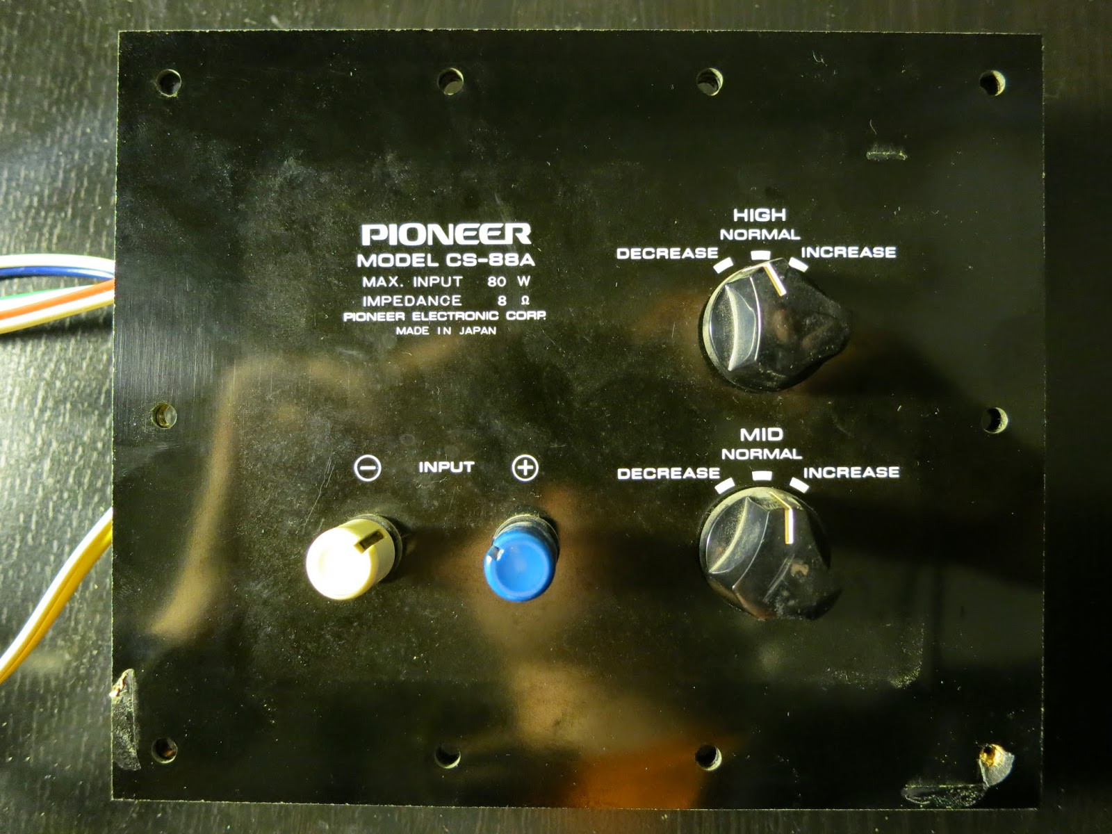 Rear view of the Pioneer CS-88a crossover showing adjustment knobs and speaker wire terminals
However, capacitors are another story. These components are known to degrade over time, impacting audio quality. While you could meticulously test each capacitor, given the age of these Pioneer CS-88a speakers and the effort already invested in accessing the crossover, replacing them is a proactive and highly recommended step. The original capacitors in the CS-88a crossover are labeled with their capacitance values in microfarads (uF). For those seeking a detailed schematic, resources like AudioKarma offer valuable schematics for the Pioneer CS-88a, outlining capacitor values such as C1 (50 uF), C2 (30 uF), C3 (5 uF), C4 (3 uF), and C5 (1 uF). It’s common with vintage equipment, and even some modern designs, that finding exact capacitor values can be challenging. This often necessitates combining capacitors in parallel to achieve the desired capacitance.
While specific links to components used in the original project may become outdated, readily available online retailers like Parts-Express (or similar audio component suppliers) offer a wide selection of non-polarized electrolytic capacitors suitable for speaker crossovers. Non-polarized electrolytic capacitors are generally recommended as replacements in these applications, mirroring the original design of the CS-88a crossover. A voltage rating of 100V for replacement capacitors is typically sufficient and safe for this application.
To achieve the precise capacitance values needed for the Pioneer CS-88a crossover recap, consider these capacitor combinations:
- C1 (50 uF): Utilize a single 50 uF capacitor.
- C2 (30 uF): Combine two 15 uF capacitors in parallel.
- C3 (5 uF): Combine a 1 uF and a 4 uF capacitor in parallel.
- C4 (3 uF): Combine two 1.5 uF capacitors in parallel.
- C5 (1 uF): Use a single 1 uF capacitor.
Therefore, for a complete recap of two Pioneer CS-88a crossovers (stereo pair), you will need the following components:
- 2 x 50 uF capacitors
- 4 x 15 uF capacitors
- 2 x 4 uF capacitors
- 4 x 1.5 uF capacitors
- 4 x 1 uF capacitors
It’s always wise to order a few extra capacitors of each value to account for any accidental damage or errors during the process. Once you have gathered all necessary parts, you can begin disassembling the crossover for capacitor replacement. Start by disassembling the speaker wire binding posts to simplify handling the crossover board. Remove the plastic backplate, and carefully mark the solder joints associated with each capacitor. You might notice existing quality control markings (often red dots) which can also serve as reference points.
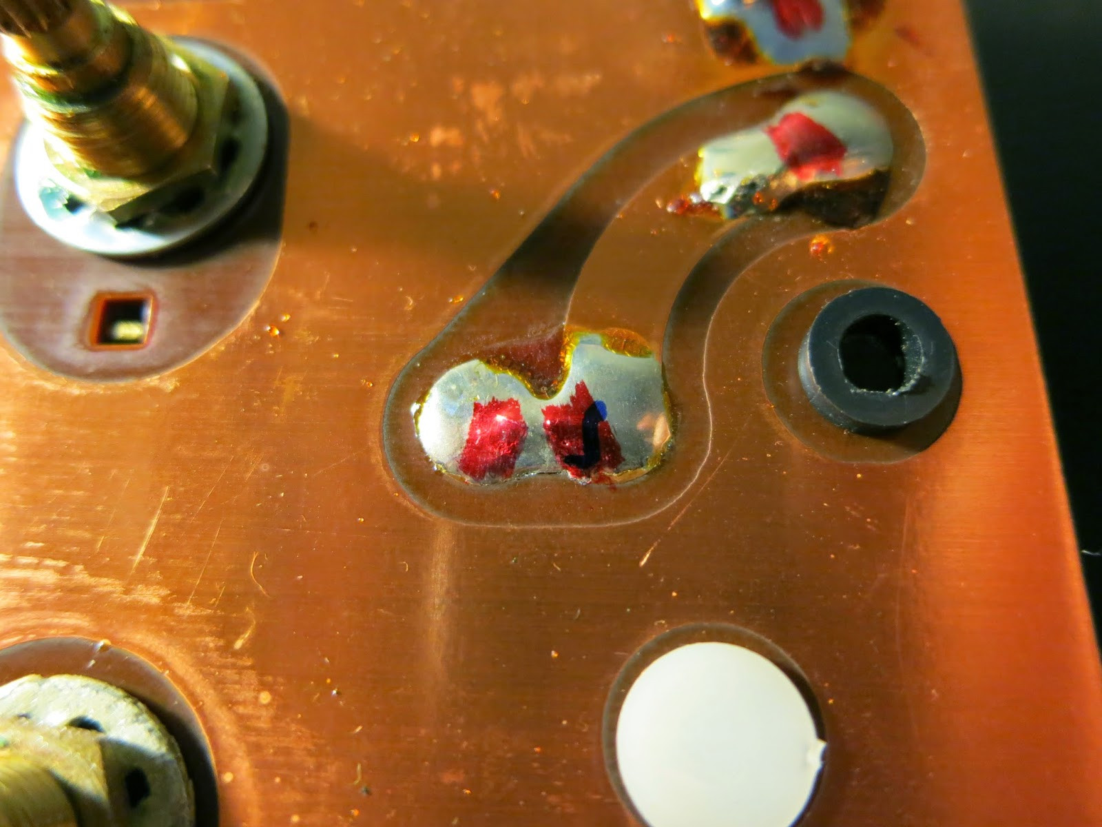 Marked solder points on the Pioneer CS-88a crossover board before capacitor removal
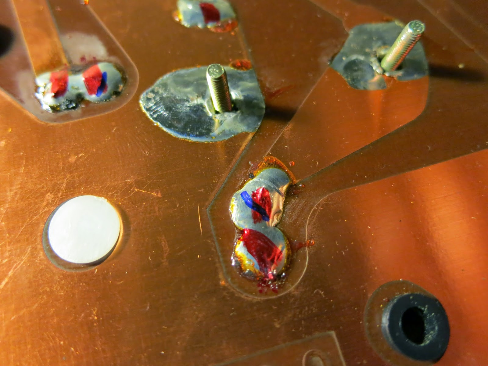 Close-up of solder joint markings on the vintage Pioneer CS-88a crossover unit
With the solder joints marked, proceed to carefully cut the leads of each capacitor. Use a sharp tool like a razor blade or scalpel to slice through the adhesive underneath each capacitor. This will loosen them, allowing you to gently rock each capacitor back and forth with pliers to break them free. If resistance is encountered, reapply the cutting tool to further loosen the glue and repeat the rocking motion. Persistence is key, and multiple iterations might be necessary to remove the old capacitors. Next, use a soldering iron and a desoldering tool (spring-loaded vacuum type is effective) to remove the majority of the solder from each marked joint. Once most of the solder is removed, grasp the remaining capacitor lead with pliers and apply heat to the solder joint while gently pulling to extract the lead completely.
Ideally, removing the old adhesive residue would be the next step. However, aged adhesive can be remarkably resistant to solvents and difficult to remove manually. Instead of attempting complete removal, focus on scraping away enough adhesive with your cutting tool to create a reasonably flat surface for gluing the new capacitors.
After preparing the surface, take this opportunity to clean the multi-position switches on the crossover. Apply contact cleaner to these switches and rotate them back and forth several times (reinstalling the knob can aid in this process). Allow the cleaner to fully dry before proceeding.
Reassembly is essentially the reverse of disassembly. When replacing a single capacitor with a parallel combination of two, you might find that the existing holes are not large enough for both leads. In such cases, wrap the lead of one capacitor tightly around the lead of the other, close to the capacitor body. Solder these leads together, and then trim the excess lead, leaving a single combined lead to insert into the circuit board hole.
Apply a small amount of adhesive (such as Liquid Nails or Shoe-Goo, or any similar rubbery adhesive) to the base of each new capacitor. Insert the capacitor leads through the correct holes on the crossover board, ensuring you are placing the correct capacitor values in their designated positions. Remember that these capacitors are non-polarized, so lead orientation is not critical. Orient the capacitor labels so they are visible; this can be helpful for future servicing.
Flip the crossover board and solder the capacitor leads to the marked solder joints. Once all capacitors are soldered in place, clip any excess lead length. Allow at least an hour for the adhesive to fully cure before handling or reinstalling the crossovers.
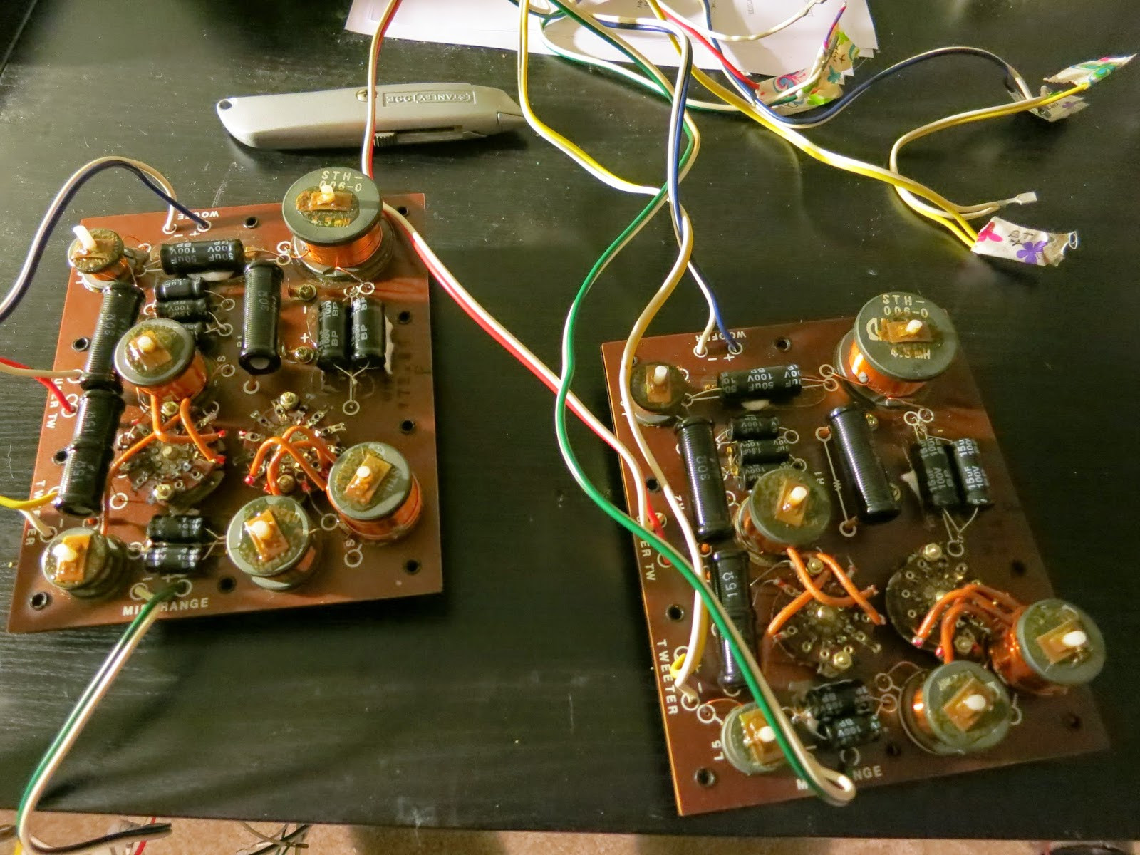 Recapped Pioneer CS-88a crossover units ready for reinstallation in the speaker cabinets
Once the adhesive is dry and the solder has cooled, you can begin reassembling your Pioneer CS-88a speakers. Snap the plastic backplate back onto the crossover assembly, and reassemble the speaker wire binding posts. Reinstall the completed crossover unit back into the speaker cabinet, ensuring it is oriented correctly (writing facing upwards). Finally, reassemble the speaker drivers in the reverse order of disassembly, carefully reconnecting the labeled wires to each driver.
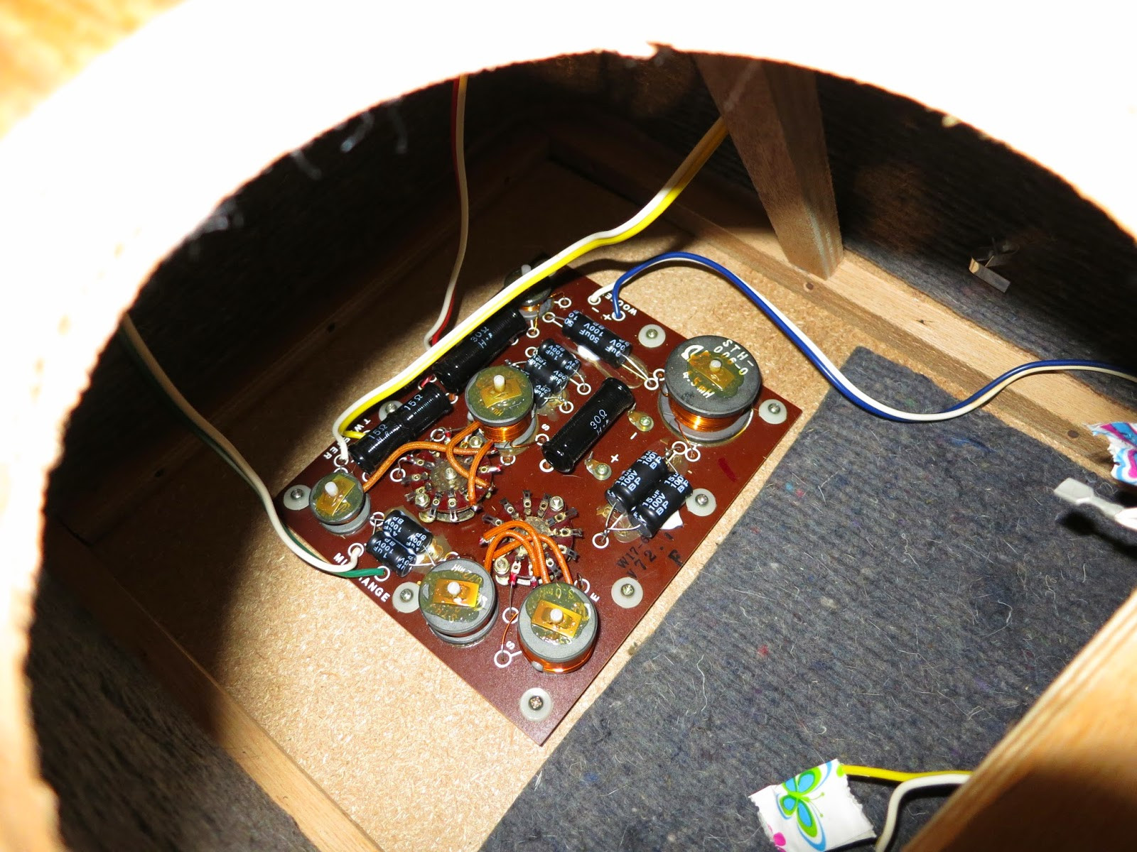 Pioneer CS-88a recapped crossover installed back in the speaker cabinet ready for driver reassembly
At this stage, your revitalized Pioneer CS-88a speakers, now featuring recapped crossovers, are ready to be connected to your audio system for testing. Take a moment to appreciate the accomplishment of restoring these classic speakers and enjoy the enhanced audio performance.


