
Upgrading your car’s stereo system can dramatically enhance your driving experience, and the Pioneer AVH-2330NEX is a fantastic choice for those seeking advanced features and seamless smartphone integration. This guide provides a step-by-step walkthrough for installing the Pioneer AVH-2330NEX, along with the AVH-2300NEX and MVH-2300NEX models, ensuring a smooth and successful DIY project. Whether you’re looking to enjoy Apple CarPlay, Android Auto, or simply improve your car’s audio quality, this guide will help you through every stage of the installation process.
What You’ll Need for Your Pioneer AVH-2330NEX Install
Before you begin, gather all the necessary parts and tools. Having everything ready will streamline the installation and prevent frustrating interruptions. Here’s a comprehensive list of what you’ll need to install your Pioneer AVH-2330NEX or similar NEX head unit:
- Pioneer AVH-2330NEX Head Unit (or AVH-2300NEX, MVH-2300NEX)
- Bezel Kit: This provides a clean, flush mount for your new head unit in your car’s dashboard. While technically optional, it significantly improves the aesthetics of your installation.
- USB Retention Cable: Allows you to maintain the functionality of your car’s factory USB port with your new Pioneer unit.
- Micro Bypass: Essential for bypassing Pioneer’s parking brake lockout feature. This enables access to certain head unit functions without engaging the parking brake, enhancing usability.
- Wiring Harness: A custom wiring harness from Crutchfield (strongly recommended) will make the wiring process plug-and-play, saving time and minimizing potential errors. It also preserves your car’s original wiring harness, which is beneficial if you ever decide to revert to the stock stereo.
Tools Required:
- Dremel tool with sanding or cutting bit (for modifying bezel kit brackets)
- 10mm socket wrench with extension (for removing head unit bolts)
- Phillips head screwdriver (for bracket screws and panel screws)
- Flathead screwdriver (for prying panels and trim)
- Wire taps or soldering equipment (for micro bypass connection)
- Heat shrink tubing or electrical tape (if soldering wires)
- Trim pry tools (optional, but highly recommended for removing plastic panels without damage)
- Super glue (optional, for microphone mount modification)
- Work light (for better visibility)
Step 0 – Preparing the Bezel Kit Brackets
Before heading to your car, preparation of the bezel kit brackets is crucial. The plastic brackets included with the bezel kit often require modification to fit correctly around the stock metal brackets.
- Identify Modification Areas: Refer to the instructions provided with your bezel kit to understand the areas needing modification. These are typically sections that need to be trimmed to accommodate the stock brackets.
- Use a Dremel Tool: Employ a Dremel tool with a sanding or cutting bit at a low power setting. Sanding bits are effective for gently melting and removing plastic.
- Trim Carefully: Gradually remove plastic from the identified areas, comparing the modified bezel brackets to the stock brackets frequently to ensure a proper fit. Aim for a smooth, clean finish, as shown in the example images.
- Test Fit: After initial trimming, test fit the bezel brackets with the stock brackets. If they don’t sit flush or encounter interference, continue trimming small amounts of plastic until a snug and correct fit is achieved.
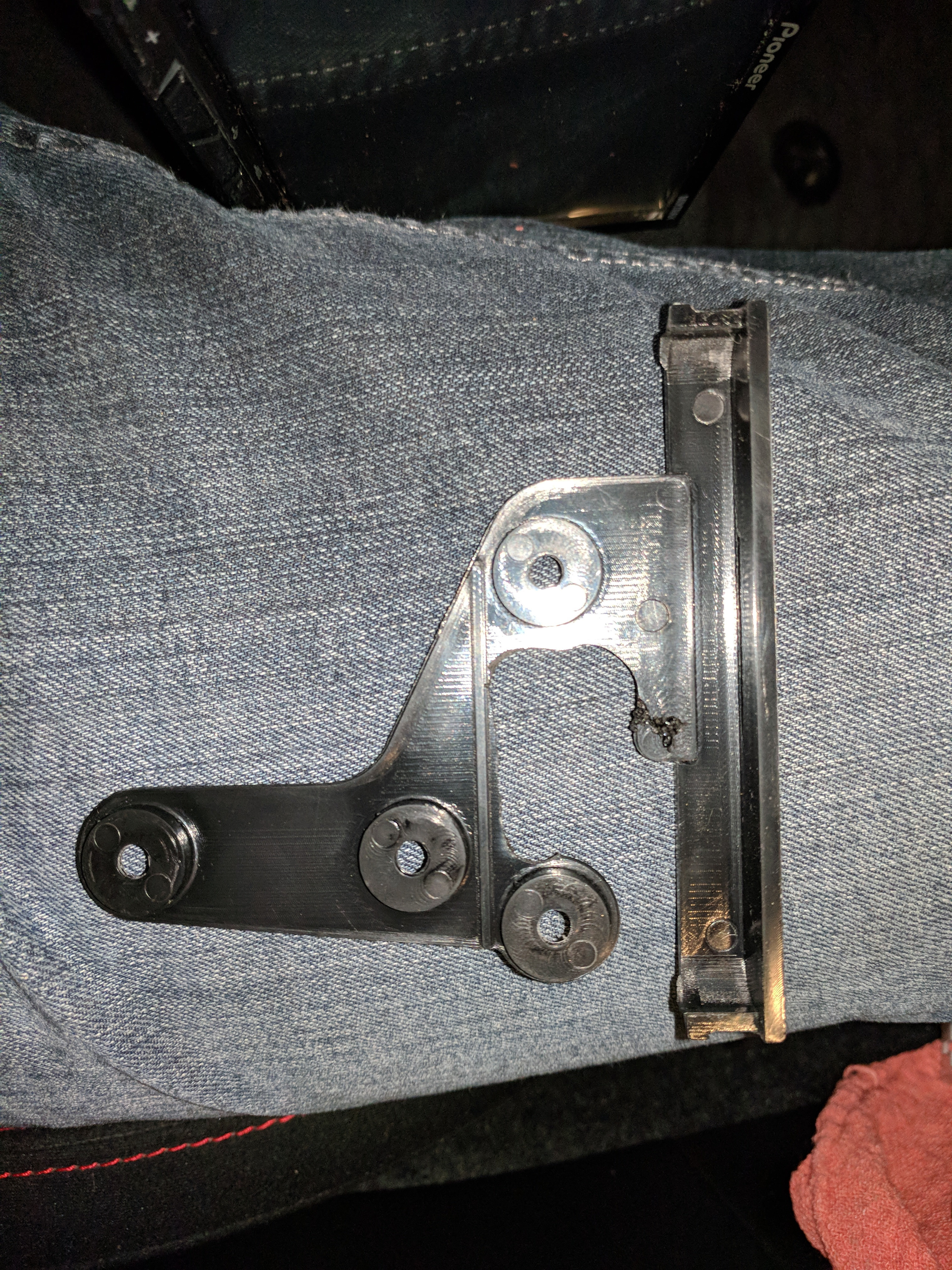 Modified plastic brackets from the bezel kit, trimmed to fit stock car brackets
 Close up view of trimmed plastic bezel kit brackets, ready for installation
Step 1 – Removing the Stock Head Unit
Now, let’s proceed to remove your car’s factory head unit. Remember to work carefully to avoid damaging any interior components.
- Remove Passenger Side Cover: Begin by using trim pry tools to carefully remove the plastic cover on the passenger side of the dashboard. This step provides easier access to the center cover. Insert a pry tool at the edge of the panel and gently apply pressure to release the clips.
- Remove Center Cover: Next, remove the center plastic cover surrounding the stock head unit. Again, use pry tools to gently release the clips holding the cover in place. Work your way around the edges, applying even pressure to avoid breaking the plastic. If you don’t have pry tools, you can use your fingers to grip the panel firmly at the top and bottom, using your thumbs to pull the bottom edge tabs first.
 Removing passenger side plastic panel with trim tools
 Removing center console plastic panel to access stock head unit
- Remove Head Unit Bolts: Once the plastic panels are removed, you’ll see four 10mm bolts securing the stock head unit. Use a 10mm socket wrench with an extension to carefully remove these bolts. Place the bolts in a safe place for reassembly later.
 Location of 10mm bolts securing the stock head unit bracket
- Protect Shifter and Trim: Before pulling out the head unit, place a cloth over your car’s shifter and any surrounding silver trim pieces. This precaution will prevent scratches as you maneuver the head unit out and disconnect the wiring.
- Disconnect Stock Head Unit Connections: Gently pull the stock head unit out slightly to access the wiring connections at the back. Carefully disconnect all wiring harnesses, antenna cable, and any other connections. Most connectors have clips that need to be pressed to release them.
- Remove Stock Brackets: After disconnecting everything, use a Phillips head screwdriver to remove the stock metal brackets attached to the sides of the factory head unit. There are typically four screws per bracket. Set the stock head unit and brackets aside safely.
 Protecting center console trim with a cloth before removing head unit
 Removing stock metal brackets from the side of the factory head unit
Step 2 – Attaching Brackets to the New Pioneer AVH-2330NEX Head Unit
Now, prepare your new Pioneer AVH-2330NEX for installation by attaching the stock metal brackets and the modified bezel kit brackets.
- Attach Stock Metal Brackets: Take the stock metal brackets you removed from the original head unit and attach them to the sides of your new Pioneer AVH-2330NEX. Ensure you place the correct bracket on each side (marked LH for left hand, RH for right hand). The brackets should align with small bumps on the head unit for proper positioning.
- Position Bezel Kit Brackets: Place the modified plastic bezel kit brackets over the stock metal brackets, aligning the screw holes. This step will reveal if your earlier Dremel work was sufficient. The bezel brackets should fit flush against the stock brackets without any obstruction.
- Secure Brackets with Screws: Use the flat-bottomed screws included with the bezel kit to secure the plastic bezel brackets to the stock metal brackets. Typically, six screws are sufficient, distributed as shown in the example image. You may also be able to reuse the stock screws, but the provided screws are usually ideal.
- Handle with Care: Be careful when handling the assembled brackets, as the plastic bezel brackets can be fragile. Avoid applying excessive force that could snap them.
 Assembling bezel kit brackets and stock metal brackets onto the new head unit
Step 3 – Hooking Up the Micro Bypass
The micro bypass is essential for unlocking the full functionality of your Pioneer AVH-2330NEX by circumventing the parking brake safety lockout.
- Identify Wires: Locate the green “Parking Brake” wire on the Micro Bypass and the lime green “Parking Brake” wire on your Crutchfield wiring harness. Also, identify the blue “Remote Turn-On” wire and the black “Ground” wire on both the Micro Bypass and the wiring harness.
- Connect Parking Brake Wire: Connect the green parking brake wire from the Micro Bypass to the lime green parking brake wire on the wiring harness. You can use wire tap connectors or solder the wires together. If soldering, ensure you insulate the connection with electrical tape or heat shrink tubing.
- Connect Remote Turn-On Wire: Connect the blue wire from the Micro Bypass to the blue “Remote Turn-On” wire on the wiring harness. Be cautious, as there may be other blue wires on the harness. Connect to the one that is designated for remote turn-on, not those looping back or going to the antenna.
- Connect Ground Wire: Connect the black wire from the Micro Bypass to the black “Ground” wire on the wiring harness. Ensure a secure and reliable ground connection.
 Wiring up the Micro Bypass module to the Crutchfield wiring harness – Parking Brake wire connection
 Wiring up the Micro Bypass module to the Crutchfield wiring harness – Remote Turn-On wire connection
 Wiring up the Micro Bypass module to the Crutchfield wiring harness – Ground wire connection
Step 4 – Connecting the Wiring Harnesses
With the Micro Bypass wired, it’s time to connect the main wiring harnesses. A custom Crutchfield harness simplifies this process significantly.
- Plug-and-Play Connections: Your custom Crutchfield wiring harness should feature connectors that directly match the connectors from your car and the Pioneer AVH-2330NEX. Identify the matching plugs and connect them securely. Each plug should typically only fit into its corresponding socket.
- Steering Wheel Controls (If Applicable): If your car has steering wheel controls, your Crutchfield harness should include a provision for connecting them. In the example image, a circled connector is shown as unused, representing steering wheel controls in a car without this feature. If you have steering wheel controls and your harness doesn’t seem to accommodate them, contact Crutchfield for support.
 Connecting the plug-and-play Crutchfield wiring harness to the car's harness
 Unused connector in wiring harness, potentially for steering wheel controls
Step 5 – Connect the USB Retention Cable
If you purchased a USB retention cable, connecting it is straightforward and allows you to retain your factory USB port functionality.
- Locate Gray Connector: Find the square, gray connector on your car’s wiring that corresponds to the factory USB port.
- Connect Retention Cable: Plug the USB retention cable into this gray connector. The other end of the retention cable will typically plug into the USB input on the back of your Pioneer AVH-2330NEX.
 Connecting the USB retention cable to the factory USB port connector
Step 6 – Running the Microphone
For improved voice clarity with features like hands-free calling and voice commands, using the aftermarket microphone included with the Pioneer AVH-2330NEX is recommended.
- Remove Stock Microphone: Locate the stock microphone in your car (often in the overhead console near the map lights). Gently pry it out of the ceiling. Disconnecting the stock microphone connector can be tricky and may require reaching up into the opening. Removing the interior light fixture may provide better access.
- Unplug and Remove Stock Microphone: Once you can access the connector, unplug the stock microphone. Remove the microphone from its mount by releasing any tabs or clips.
- Modify Microphone Mount (Optional): If you want to use the stock microphone location for a cleaner look, you can modify the stock mount to hold the aftermarket microphone. Use a Dremel to adjust the clip and then super glue the aftermarket microphone to the modified stock mount.
- Route Microphone Cable: Push the cable of the aftermarket microphone through the hole in the headliner where the stock microphone was located. Carefully run the cable along the windshield edge (tucking it into the headliner), down the A-pillar, and behind the glove box, finally reaching the area behind the head unit.
- Access Behind Glove Box: To ease cable routing behind the glove box, open the glove box fully, then squeeze the sides inwards to allow it to open further, past its normal stop. This provides more access to route the cable behind.
 Aftermarket microphone glued to the modified stock microphone mount
 Close up of aftermarket microphone mounted in stock microphone housing
 Side view of aftermarket microphone installed in modified stock mount
 Top view of aftermarket microphone secured in the stock microphone mount
 Routing the microphone cable along the windshield and headliner
 Microphone cable routed down the A-pillar trim
Step 7 – Hooking Up the Reverse Light Wire (Optional)
Connecting the reverse light wire is only necessary if you have or plan to install a backup camera with your Pioneer AVH-2330NEX. If not, you can skip this step.
- Remove Lower Steering Wheel Panel: Start by removing the plastic panel beneath the steering wheel. Open the driver’s side door and pop off the side cover of the dashboard to reveal a Phillips screw. Remove this screw and another Phillips screw located underneath the panel, towards the center console.
- Detach Panel Clips: Carefully pop off the panel by applying firm, even pressure around the edges to release the clips. Work your way around the panel until it is free.
- Disconnect Switches: Disconnect any switches on the panel, such as trunk release and dimmer switches. Set the panel aside.
- Route Purple Wire: Run the purple “Reverse Trigger” wire from your wiring harness down behind the dashboard and towards the driver’s side of the center console. Route it carefully, ensuring it doesn’t interfere with pedals or hang down. Guide it towards the hood release lever area.
- Access Hood Release Cover: Use a flathead screwdriver to pop out the plastic rivet securing the cover around the hood release lever. Once removed, you can partially “swing open” the cover for access to the wiring behind it.
- Locate Reverse Light Wire: Crawl under the dashboard to see the back side of two white connector blocks. Look for an ORANGE wire with SILVER/WHITE markings on one of these connectors. This is typically the reverse light wire.
- Tap into Reverse Light Wire: Use a wire tap connector to connect the purple reverse trigger wire from your harness to the identified orange/silver reverse light wire. Ensure a secure connection.
- Leave Panels Loose: For now, leave the removed panels loose in case you need to revisit this connection during testing.
 Removing the side panel near the driver's side door
 Phillips screw location under the steering wheel panel
 Second Phillips screw location under the steering wheel panel
 Popping off the steering wheel lower panel clips
 Removing the lower steering wheel panel
 Lower steering wheel panel fully removed
 Disconnecting switches from the lower steering wheel panel
 Routing the purple reverse trigger wire behind the dash
 Popping out the plastic rivet on the hood release cover
 Swinging open the hood release cover for wiring access
 Tapping into the orange/silver reverse light wire
Step 8 – Hooking Everything Up
With all wiring preparations complete, it’s time to connect everything to your Pioneer AVH-2330NEX and prepare for testing.
- Position Head Unit: Carefully position the Pioneer AVH-2330NEX near the dashboard opening, ensuring the protective cloth is still in place to protect the trim.
- Connect All Connections: Connect the following to the back of the head unit:
- Main black wiring harness connector
- USB retention cable
- Microphone (3.5mm jack)
- Reverse camera RCA cable (if applicable, connect to the correct “Rear Camera In” RCA input – typically yellow)
- Antenna cable
- Refer to Diagram: Use the wiring diagram included with your Pioneer AVH-2330NEX to confirm the correct inputs for each connection, especially the reverse camera RCA.
 Wiring diagram showing reverse camera RCA input location
- Tuck Wires and Slide in Head Unit: Gently tuck the loose wiring back into the dashboard opening. There may be limited space, so organize the wires as neatly as possible. Carefully slide the Pioneer AVH-2330NEX into the dashboard slot.
 Connecting all wiring harnesses to the back of the Pioneer head unit
 Sliding the Pioneer head unit into the dashboard opening
Step 9 – Testing Your Pioneer AVH-2330NEX
Before fully reassembling your dashboard, thorough testing is essential to ensure everything is working correctly.
- Power On Test: Turn your car’s ignition to the ACC (Accessory) position. The Pioneer AVH-2330NEX should power on. Proceed through the initial setup prompts, such as language selection.
- Basic Functionality Test: Test basic functions like the radio. If you have a USB drive or phone handy, test USB playback and smartphone integration features like Android Auto or Apple CarPlay. Connect your phone via USB; Android Auto should launch automatically (ensure the app is installed on your phone).
- Micro Bypass Verification: Navigate through the head unit menus to find the “Restore Settings” or similar option. If this option is accessible (not grayed out), the Micro Bypass is likely wired correctly. If it’s grayed out, re-check your Micro Bypass wiring in Step 3.
 Pioneer AVH-2330NEX powered on and displaying setup screen
 "Restore Settings" option in Pioneer menu, indicating correct Micro Bypass wiring
- Reverse Camera Test (If Applicable): Turn the ignition to the ON position (without starting the engine). Engage the parking brake and shift your car into reverse. The head unit should automatically switch to the reverse camera display, showing a warning message and the camera view.
- Camera Settings Check: If the reverse camera doesn’t activate, go to the head unit’s Settings (gear icon) -> Setup (tool icon) -> Camera settings. Ensure “Backup Camera” is turned ON and that “Camera Polarity” is set to “Battery,” not “Ground.” Adjust “Parking Assist Guide” as needed based on your camera’s features (if your camera has built-in guidelines, you can turn this feature off on the head unit).
- Repeat Reverse Test: Shift in and out of reverse a few times to confirm the reverse camera is working reliably. If issues persist, revisit Step 7 and check your reverse light wire connection.
- Turn Ignition Off: Once you are satisfied that all tested functions are working correctly, turn the car’s ignition off.
 Reverse camera display on Pioneer AVH-2330NEX during testing
 Camera settings menu on Pioneer AVH-2330NEX for backup camera configuration
Step 10 – Reassembly
With successful testing, you can now reassemble the dashboard and finalize the installation.
- Hood Release Cover Panel: Starting with the hood release cover panel, swing it back into position and firmly push it to secure it. Reinsert the plastic rivet to hold it in place.
 Reinstalling the hood release cover panel
- Lower Steering Wheel Panel: Reinstall the lower steering wheel panel in reverse order of removal. Reconnect any switches to the panel, align the tabs, and push it back into place, ensuring all clips are engaged. Replace the two Phillips screws and the side plastic panel near the driver’s door.
 Reconnecting switches to the lower steering wheel panel
 Reinstalling the lower steering wheel panel into the dashboard
Second Phillips screw location under the steering wheel panel
Phillips screw location under the steering wheel panel
 Reinstalling the side panel near the driver's door
- Glove Box Reinstallation: If you opened your glove box past its normal stop, reposition it by hooking the bottom hinges onto the plastic rods and pushing it upwards until it clicks back into its standard operating position. Close the glove box.
- Secure Head Unit with Bolts: Use the 10mm socket wrench and extension to reinstall the four 10mm bolts that secure the Pioneer AVH-2330NEX in the dashboard. Tighten them snugly, but avoid over-tightening.
- Replace Plastic Covers: Reinstall the center plastic cover around the head unit and the passenger side cover. Ensure all clips are properly engaged and the panels are flush.
- Final Touches: Wipe down the dashboard area to remove any fingerprints or dust.
Location of 10mm bolts securing the stock head unit bracket
 Reinstalling the center console plastic panel around the new head unit
Congratulations! You have successfully installed your Pioneer AVH-2330NEX, AVH-2300NEX, or MVH-2300NEX head unit. Now, it’s time to relax and enjoy your upgraded car audio system and the advanced features of your new Pioneer NEX receiver. Explore the menus, customize your settings, and perhaps even enjoy a movie on your crisp new display.